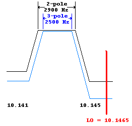
- BW of the 3-pole receive filter = 2500 Hz
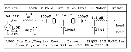
- BW of the 2-pole transmit filter = 2900 Hz
|
The 30M WARCbler PSK-31 Rig Conversion Kit By: Fred Spinner, W0FMS and Jeff Woods, W0ODS (C) Copyright 2001, Fred Spinner and Jeff Woods -- All Rights Reserved May 14, 2001 |
Part 2--
Redesign of the filters:
The redesign of the Cohn Crystal Lattice filters was an intersting endeavor. The "classic" articles on designing crystal filters are the QST article "A Unified Approach to the Design of Crystal Ladder Filters", by Wes Hayward W7ZOI in May of 1982, and the followup article "Designing and Building Simple Crystal Filters", by Wes Hayward W7ZOI in July of 1987.
These articles are a good start, but lacked some detail we needed to figure out the design of these filters. One important note for designers of crystal filters that use uncharacterized crystals: the 1982 article describes how to characterize the crystals with simple instrumentation. In our case, we were provided with complete information on 20 of the 125 crystals we recieved. So, please note that the crystal specification we used were provided by the crystal manufacturer.
The "magic bullet" was an internet web page that reverse-engineered the Small Wonders Labs SW-40+ rig's CW filter. The link to this page, http://epic.mcmaster.ca/~elmer101/cohn.html, supplied us with the needed information to design the filters.
The filters were then modeled in Spice 3, using the excellent and freely available WinSpice, http://www.winspice.com.
The crystal was modeled using the following descrete crystal characteristics:
When we went to build the rig, we noticed that crystal variances
made it difficult to match the start and end of the passband from one filter
to the next (and more importantly the TX filter from the RX filter).
This is probably the case with the PSK-80 as well. In our case, however,
we have the freedom to set the passband bandwidths of both of the filters
seperately. An obvious solution to this minor problem is to widen
up the transmit filter a little more than the receive filter, but still
have it be narrow enough to reject the LO. The operator will see
the response of the narrower 3-pole filter on the FFT display of their
favorite PSK program, making it look as if that is the rigs response in
both TX and RX. (Soapbox: a better solution would be to use one filter,
and switch with PIN diodes-- this is out of scope for the "conversion"
kit. -- it would use less crystals and be cheaper as well.)
 |
|
Given the tables from the "elmer101" webpage, ultimately taken from Zverev's "Handbook of Filter Synthesis" the two following filters were designed. (Note the 0.70711 factor is valid both for the 2 and 3 crystal filters):
Ccoupling = C1 * F0 / (BW * 0.70711) = 20.20e-15 * 10141500 / (2500
* 0.70711) = 118 pf ~= 120 pf for the 3-pole receive
filter.
Ccoupling = C1 * F0 / (BW * 0.70711) = 20.20e-15 * 10141500 / (2900
* 0.70711) = 99.9 pf ~= 100 pf for the 2-pole transmit
filter.
This value will give us a 3 dB bandwidth of 2500 Hz for the 3-pole receive filter, and 2900 Hz for the 2-pole transmit filter. Now, it is absolutely critical with a Cohn Crystal filter to impedance match the filter for a good shape and response! This was determined by:
Zfilter = 2*pi * L * BW / q, where q is a factor of 1.4141 for the 2-pole and a factor of 1.0000 for the 3-pole filter.
Two pole Zfilter = 2 * pi * 0.01219 * 2900 / 1.4141 =
157 Ohms
Three Pole Zfilter = 2 * pi * 0.01219 * 2500 = 188 Ohms
To match this to the 1500 Ohms, a L-match was used at both ends. We will leave this design step up to the reader, as it is covered in many computer programs (such as HAMCALC LADDER2) and the ARRL Handbook.
The final filter designs for 1500 Ohms looks like as follows:
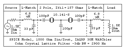
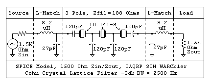
After the final redesign, we used different impedance values for the "WARCbler" -- On receive, we rebiased the input amplifier so the impedance the filter sees is 180 Ohms, near its "natural" impedance of 188 Ohms. Therefore, no L-match was necessary on it's input. The same 188 -> 1500 Ohm match was used at the filter output to match to the SA-612 Mixer.
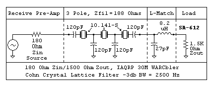
For the skeptical:
We also designed the following 50 Ohm matched filters to look at the response on a HP Network Analyzer. Here are the 50 Ohm designs. NOTE-- both designs depicted below are 2500 Hz BW designs:
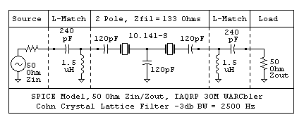
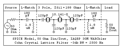
The actual measured response of the ORIGINAL 2-pole 2500 Hz, 50 Ohm, filter is depected in the following graphs. This filter was breadboarded up to make sure our calculations were sane. The conversion kit will have the 2-pole filter BW set for 2900 Hz as above:
Filter response, 10 dB/div (S12=S21), insertion loss is around 1 dB:
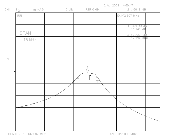
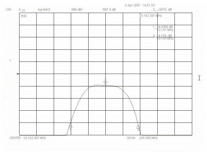
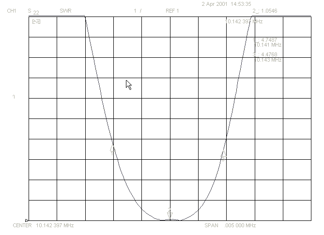
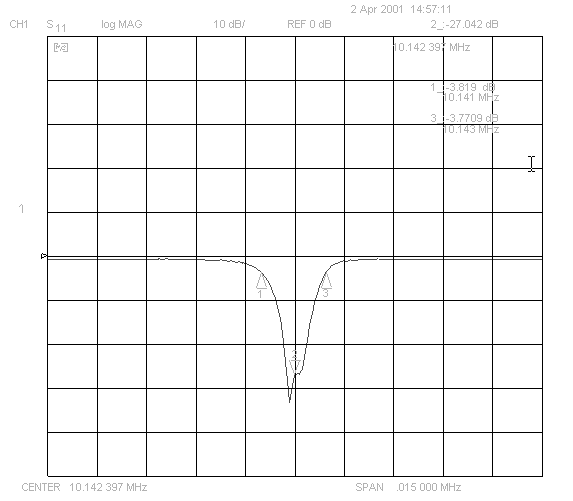
We have not yet constructed and tested the 3-pole filter, due to the tight schedule we had to make to make the deadline for Arkiecon. However, I think we belive in the mathmatics enough now (WOW!), and the finished "Alpha 30m WARCbler" seem to show adequate response out of the 3-pole receive filter.
Next: Other
circuit modifications to transform a PSK-80 into a PSK-30 WARCbler.